Basic HTML Version


Features
Here's
an
alternative
mounting
choice
for
your
cylinders.
Centered
around
the design
of
the
smooth bodied,
nose
mount
cylinders
on
page
ó,
Víatson
flat
mount
cylinders are available
in both
single
and double
acting
models
with
strokes
up to
2' in
1/4"
increments.
As
an
option
ali
cylinders can
be
ordered
with
electroless nickel
plating for
a
bright
appearance
and corrosion protect¡on
in
harsh
environments.
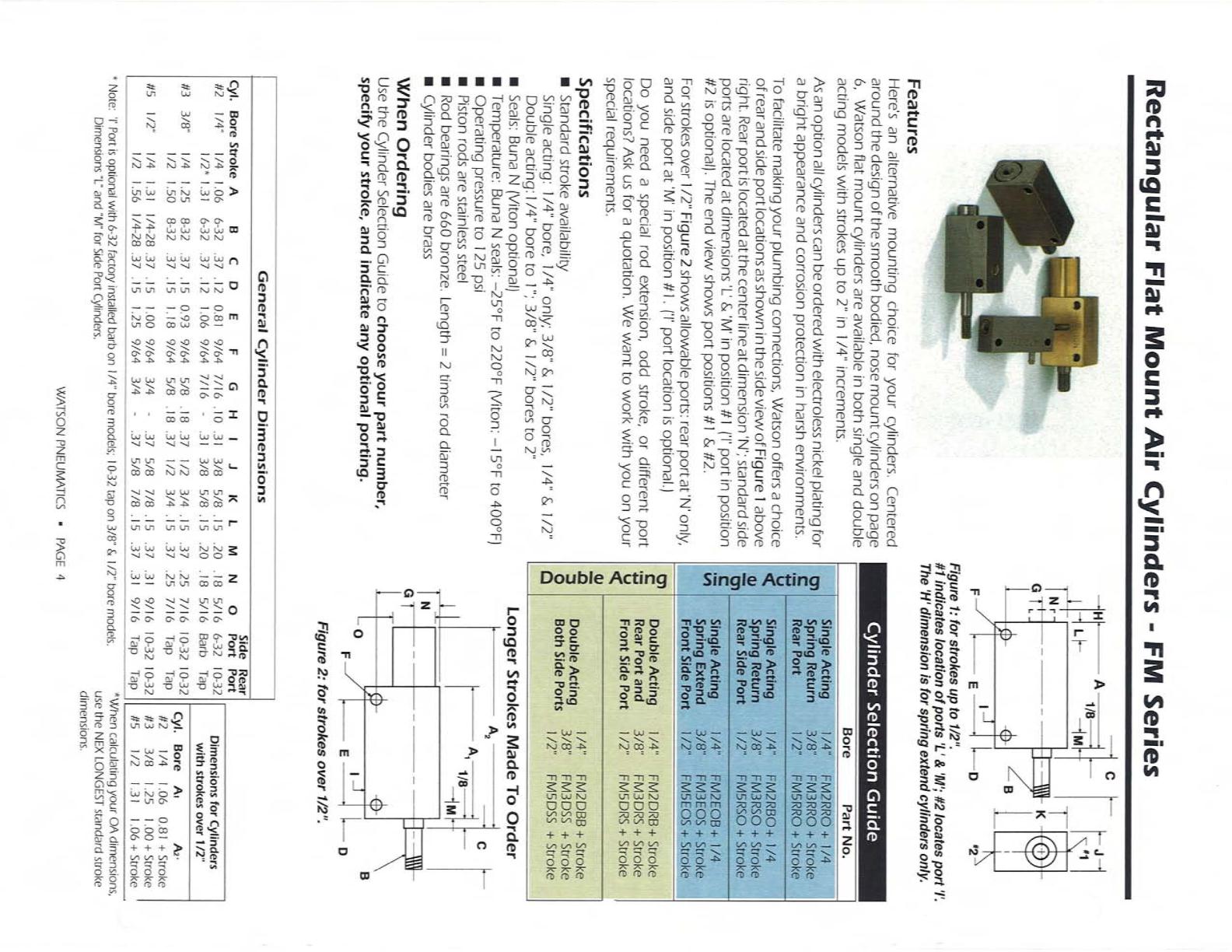
To
facilitate making
your plumbing
connections,
Watson
offers
a
choice
of rear
and
side
port iocations
as
shown
in
the side
view of
Figure
1
above
r¡ght.
Rear
port
is
located
at
the center
line at
dimension
'N'; standard side
ports are located at
dimensions
L'
& '
M' in pos¡tion
#
I
('l
port in
position
#2
is
optional).
The
end view shows
port
positions
#l
& #2.
Forstrokes over
I
/2"
Figure
2
shows
allowable
ports:
rear
portat'N'
only,
and
side
port
at'
M
in
position
#1.
l'l'
port
location
is
optional.)
Do
you
need
a
spec¡al
rod
extension,
odd
stroke,
or
difFerent
port
locations? Ásk us
for a quotation.
We
want
to work
with you
on your
spec¡al
requirements.
Specifications
r
Standard stroke
availability
Singleacting:1/4"
|¡ore,
l/4"
only;3/8"
&
1/2"
bores, 1/4"
&
t/2"
Double
act¡ng:
I
/4"
l:ore
to
1":
3/8"
&
1
/2"
bores
to
2"
I
Seais:
Buna
N
(Viton
optional)
I
Temperature:
Buna
N
seals:
-25"F
to
220"F (Viton:
-l5oF
to
400"F)
r
Operating
pressure
to
125
psi
I
Piston rods are
stainless steel
I
Rod
bearings
are
660
bronze. Length =
2 times
rod
diameter
r
Cylinder bodies are
brass
When Ordering
Use
the
Cyiinder Selection
Guide
to choose
your part
number,
specify
your stroke,
and indicate any
optional
port¡ng.
* Note:
'l'
Port
is
opt¡onal
with
6-32 factory instafled barb
on l/4"
bore models; l0-32 tap on 3/8"
& l/2"
bore
models
Dimensions
"1"
and
"M" for
Side
Port Cylinders.
#1 indicates
location of
ports'L' &'
M';
#2
locates
port'l'.
The'H'
dimension is for spring extend cylinders only.
[-o
Figure
2:
tor
strokes over
1/2".
l-
4
cyt.
#2
#3
#5
*When
calculating
your
OA dimensions,
use
the
NEX LONGEST
standard stroke
dimensions.
Bore
1/4
3/8
t/2
42,
0.8I
+
Stroke
1.00
+
Stroke
1.0ó
+
Stroke
Bore
Part No.
t/4"
i¡nneo*
v+
3/8"
FM3RSO
+
Stroke
.l/2"
FMSRSO
+,
Stroke
Oì
c
'aJ
(,
g
c¡
J
o
o
Double
Act¡ng
I
/4"
FMZDRB
+
Srroke
Rear
Port
and 3/8"
FM3DRS
+
Stroke
Front
S¡de
Port
I
/2
FM5DRS
+
Stroke
#rírl;åï'll
,
üi,, iffiíãäiiË[
Longer
Strokes Made To
Order
Cyl.
Bore
Stroke A
#2 1/4"
1/4
I
.06
1/2*
1
.31
#3
3/8"
1.25
8-32
.37
.15
1.50
B-32 .37
.15
#5 1/2"
I
/4
1
.3t
I
/4-28
,37
1/2
1
.56
1/4-28
.37
General
Cylinder
Dimensions
EFGH
0.Bl
9/64
7/16.10
1
.06 9/64
7
/16
0.93
9/64
5/B
.18.37
1.tB
9/64
5/8
.18
.37
1.00
9/64
3/4 -
.37
5/B
7/B
,15
.37
1.25
9/64
3/4 -
.37
s/8
7/8
15
37
BCD
6-32
.37
12
6-32
.37
.12
l5
l5
I
.31
.3
I
JKLM
3/B
5/B
.15
.20
3/B
5/B
.15
.20
1/2
3/4
.15
.37
1/2 3/4.15
.37
Side
Rear
N
O
Port
Port
.18 5/16
6-32
10-32
.18 5/16
Barb
Tap
.25
7/16
10-32
10-32
.25
7/16
Tap
Tap
.3
i
9/16
10,32
t0-32
.3
I
9/16
Tap
Tap
t/4
1/2
Dimensions
for
Cylinders
w¡th
strokes over
l/2"
WATSON PNEUM.ATICS
.
PAGE
4